
|
Архитектура Аудит Военная наука Иностранные языки Медицина Металлургия Метрология Образование Политология Производство Психология Стандартизация Технологии |
|
|
Архитектура Аудит Военная наука Иностранные языки Медицина Металлургия Метрология Образование Политология Производство Психология Стандартизация Технологии |
RIGHT CRANKCA SE COVER REMOVAL
Drain oil from the engine (page 2·3). Remove the exhaust pipe and brake pedal {pa,ge 5 2). Remove the brake pedal shaft bracket.
Place a jack or other adjustable support under the engine to support it.
Remove the right sub-frame. Disconnect the clutch cable.
(1) BRAKE PEDAL (2) EXHAUST PIPES
(1) CLUTCH CABLE
(2) SUB-FRAME
CLUTCH H O NDA. VT500C
Remove the lifter rod and circlip. Remove the lifter arm and return spring. NOTE
CLUTCH (!IBEARING
(2)
(3) PLATE "A"
(4) DISC "A"
(5) CLUTCH OUTER GUIDE
(16JOIL PUMP DRIVE SPROCKET
(13) PRESSURE PLATE (14) ) WASHER
(9) CLUTCH CENTER
CLUTCH r::iJ\ H O NDA VTSOOC CLUTCH REMOVAL
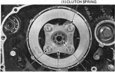
Remove the lifter plate bearing. Remove the four bolts in a crisscross pattern in 2-3 steps.
Remove the clutch lifter plate and clutch springs.
CLUTCH SPRING INSPECTION
Measure the clutch spring f ree length.
SERVICE LIMIT :39 mm (1.53 in)
Replace any spri ng that is shorter than the service limit.
Hold the clutch center with the Clutch Center Holder (07923-KE 10000).
Remove the lock nut and lock washer.
Remove the clutch center, damper seat, damper spring. clutch disa and plates and pressure plate as a unl L
(2)
(1)
CLUTCH H O NDA VT500 C
Remove the washer and clutch outer.
CLUTCH DISC INSPECTION
Replac:e the clutch discs if they show signs of scor ing or discoloration.
Measu re the disc thickness.
SERVICE LIMITS: DISC A: 2.30 mm (0.090 in) DISC B 2.60 mm (0.102 in)
Replace the discs If they are thinner than the service limits.
PLATE INSPECTION
Check for plate warpage on a surf ace plate, using a feeler gauge.
SERVICE LIMIT: 0.3-0 mm (0.012 in)
(1) CLUTCH OUTER
CLUTCH H O NDA VT500 C INSPECTION CLUTCH OUTER Chock the sl01s in the clutch outer for nicks, cuts or Indentations mede by the friction discs.
Measu re the clutctl outer 1.0.
Check the clutch outer bushing for score marks or other damage.
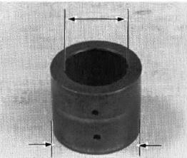
CLUTCH OUTER GUIDE
Measure the 1.0. and 0.0. of the clu tch outer guide.
SERVICE LIM IT: 1.0. 22.09 mm (0.889 In) 0.0. 31.98 mm (1.259 in)
CLUTCH ASSE MBLY Install the clutch outer guide over the mainshaft. Align the grooves in the clutch outer with the boss on the oil pump drive sprocket while tu rning the sprocket wim the chain and pushing the clu tch outer.
GUIDE
Install the washer over the mai nshaft.
NOTE
Note direction of the spring seat, spring .and plate B.
I nstall the clutch discs, clutch plates and pressure plate on the clutch center and install them on the clutch outer together.
Stack the discs and plates alternately as shown. Coat new clutch discs with engine oil.
(1) WASHER
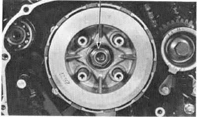
C L U T C H VT500C Hold the clutch center with the Clutch Center Holder (07923-KE 10000). Tighten the lock nut. TORQUE: 65-75 N·m (6.5-7.5 kg-m, 47-54 ft·lb)
Install the clutch springs, lifter plate and lifter plate bolts. Tighten the bolts in a crisscross pattern in 2-3 steps.
I nstall the bearing into the lifter plate.
P R IMAR Y GEAR R EMOVAL
Remove the right crankcase cover (page 7-3). Remove the clu tch (page 7-5). Remove the top and bottom pulse generator pick up. Hold the pri mary gear wi th the gear holder (07923- ME90000) and remove the bolt.
Remove the pulse generator plate and primary gear from the cran kshaft.
(1) LOCK NUT
(1)
(1) {2) BOLT (3) PULSE GENERATOR PLATE CLUTCH VTSOOC
INSTALLATION
Install the primary gear.
Align the center of two pulse generator plate teeth with the flat of the crankshaft serrations and install the plate.
Measure the pu lse coil air gap and adjust if neces sary (page 19-4).
AI R GAP: 0.3-0.9 mm (O.Gl-0.04 in)
TOR QUE: 80-100 N·m (8.0-10.0 kg ITli,58-72 ft-lb)
R emove the gear holder and install the pu l se genera tors and clutch.
|
Последнее изменение этой страницы: 2019-06-10; Просмотров: 235; Нарушение авторского права страницы
 Remove the right cran kcase cover, gasket andl dowel pins.


 CLUITCH LIFTER ARM D ISASSEMBLY
 LIFTER PLATE
 BOLT (3) LIFTER PLATE (4) BEARING
 PRESSURE PLATE (21CLUTCH CENTER


 (2) WASHER

 SE RVICE LIMIT:32.10 mm (1.263 in)

 (l ) BOSSES
 I nstall the damper spring and seat, and clutch plate B in the' clutch center.

 NOTE
NOTE Install the lock washer making sure the "OUT SIDE" mark faces out.
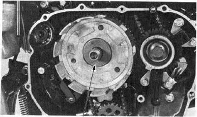


 BEAR ING (4) LIFTER PLATE
 PRIMARY GEAR
 I nstall the primary gear holder (07923-ME90000). Tighten th e primary gear bolt.